Introduction
I’m Matthew with Perspic, and in this post, we’re diving into the fundamentals of the CAN Bus physical layer. You’ll learn how data travels across the network, what those signals look like on an oscilloscope, and why the physical layer is critical to reliable communication.
If you’re just joining us, be sure to check out our previous post, where we explored the history, key features, and advantages of CAN Bus networks.
Setting Up the CAN Network Wiring
To demonstrate how CAN messages are transmitted, we’ve built a simple CAN network setup that lets us send and receive data—and visualize the signal on an oscilloscope.
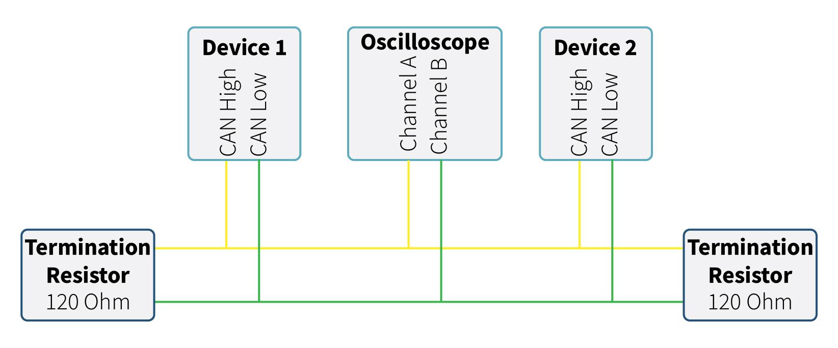
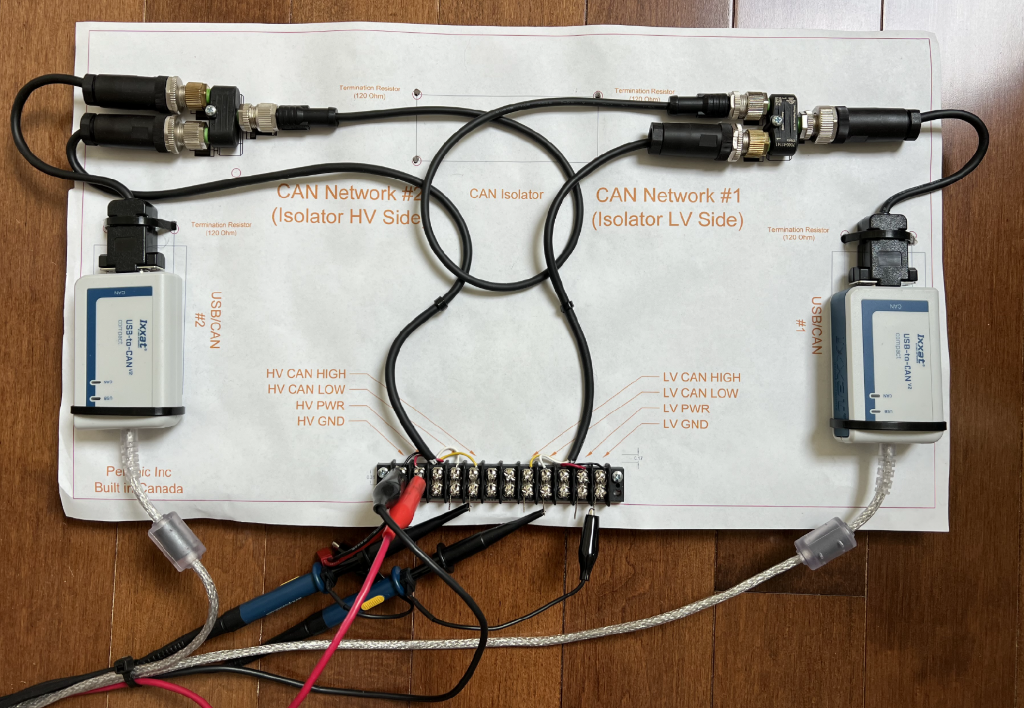
Here’s the basic setup:
- Two USB-to-CAN devices connected with approximately 1 meter of twisted-pair cable.
- 120-ohm termination resistors at each end of the bus. (hidden in the termination connectors)
- An oscilloscope connected to:
- Ground
- Channel A to CAN_H
- Channel B to CAN_L
Configuring Devices for Communication
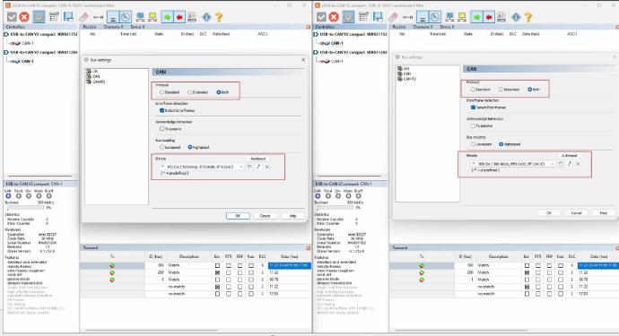
Before any data can be transmitted, all devices on the CAN network must be configured to use the same baud rate (also called the bit rate), and if necessary, the same message ID format.
The most common CAN baud rates are 125 kbps, 250 kbps, 500 kbps, and 1 Mbps. In this demonstration, our devices are set to 500 kbps. Higher baud rates allow more data to be transmitted per second but come with trade-offs: they’re more susceptible to noise and require shorter maximum bus lengths.
CAN devices generally support two message ID formats:
- Standard (CAN 2.0A): 11-bit identifiers, ranging from 0 to 2,047 (0x7FF)
- Extended (CAN 2.0B): 29-bit identifiers, ranging from 0 to 536,870,911 (0x1FFFFFFF)
While most modern devices support both formats, some older or simpler nodes might only work with the 11-bit standard format. Also, many CAN controllers maintain separate buffers for standard and extended messages. So, if you plan to use extended IDs, make sure all devices on the bus support them to avoid compatibility issues.
Understanding Differential Signaling
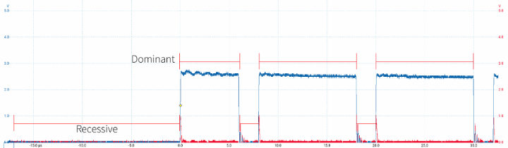
CAN Bus uses differential signaling to enhance noise immunity, making it especially reliable in harsh environments like automotive and industrial systems. Rather than relying on voltages referenced to ground, CAN transceivers only care about the voltage difference between the CAN_H and CAN_L wires. This makes the system more resistant to electrical noise and ground shifts.
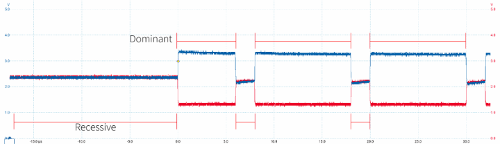
In idle or "Recessive" states, both CAN_H and CAN_L sit around 2.5 volts—this is known as the common mode voltage. When a bit is transmitted, the lines split:
- Dominant Bit (logical 0):
- CAN_H is driven high (around 3.5V)
- CAN_L is driven low (around 1.5V)
- This creates a differential voltage of ~2V
- Recessive Bit (logical 1):
- Both CAN_H and CAN_L float near 2.5V
- The differential voltage is ~0V
The key point:
- A Dominant state represents a 0
- A Recessive state represents a 1
This naming can feel counterintuitive at first—after all, we’re used to thinking of “1” as a stronger signal than “0.” But in CAN, the dominant state physically overrides the recessive one on the bus. So even if one device sends a recessive bit and another sends a dominant bit at the same time, the dominant bit wins. As we will see this is a crucial feature for how CAN arbitration works.
Why Shorts Are Problematic:
Each device on the CAN network weakly pulls CAN_H and CAN_L to approximately 2.5V when idle. Thanks to differential signaling, the bus can sometimes continue operating—though in a limited capacity—even if CAN_H or CAN_L is shorted to ground. That’s because CAN devices only measure the voltage difference between the two lines, not their absolute voltages relative to ground.
However, shorting CAN_H or CAN_L directly to GND or VCC can severely disrupt communication or even damage components.
See below for an oscilloscope capture showing signal ripple when CAN_L is shorted to ground.
Anatomy of a CAN Frame
A complete transmission of a single message on the CAN Bus is called a CAN Frame. To understand its structure, let’s examine an oscilloscope capture of one standard frame. In this example, the frame has an ID of 0x123 and carries the following data bytes:
[0x12, 0x23, 0x34, 0x45, 0x56, 0x67, 0x78, 0x89].
Let’s quickly review the purpose of the CAN bus: to transfer a packet of data from one device to another. For this to work, the receiving device must:
- Receive the data
- Understand what the data means
In a CAN frame:
- The Message ID defines the context or meaning of the data
- The Data Bytes contain the actual information to be sent or received
This separation of ID and data makes CAN highly flexible and efficient in multi-device communication. Lets break down the frame in an oscilloscope capture.
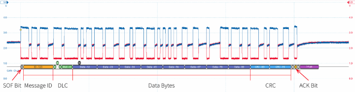
Let’s walk through the key components of a CAN frame, using the color-coded highlights you'll see in the oscilloscope view:
- Start of Frame (SOF) (grey)
- A single dominant bit that signals the beginning of a new message.
- Message ID / Arbitration ID (yellow)
- Standard CAN: 11-bit identifiers
- Extended CAN (CAN 2.0B): 29-bit identifiers
- Used for arbitration when multiple devices attempt to transmit at the same time.
- Also determines how the data should be interpreted by receivers.
- DLC (Data Length Code) (green)
- Indicates how many data bytes follow (0 to 8 for standard CAN, up to 64 for CAN FD).
- This field also includes:
- RTR: Remote Transmission Request bit
- IDE: Identifier Extension bit
- r0: Reserved bit
- Data Bytes (dark blue)
- Standard CAN: Up to 8 bytes of actual data
- CAN FD: Up to 64 bytes of data
- CRC (Cyclic Redundancy Check) (light blue)
- A checksum calculated from the data bytes to ensure message integrity.
- ACK (Acknowledgment Bit) (yellow)
- Devices that successfully receive the frame pull the bus to a dominant state to signal acknowledgment.
- Interframe Space / Wait for Next Frame (purple)
A short pause where no device should transmit. This allows the bus to remain idle before the next frame starts.
How Nodes Communicate – Arbitration
CAN Bus uses a non-destructive arbitration process to determine which device gets to transmit when multiple devices attempt communication simultaneously. It's called “non-destructive” because no data is lost—devices that loose arbitration stop transmitting without corrupting the bus or forcing a full retransmission.
Here’s how it works:
- Multiple devices may attempt to transmit simultaneously.
- Each frame begins with the Message ID, which doubles as an arbitration field.
- The device sending the lowest numerical Message ID wins arbitration and continues transmitting.
- All other devices detect the loss and back off, waiting for the next opportunity to try again.
So, how do the losing devices know they lost?
During transmission, each node is both sending and listening to the bus. If a device sends a recessive bit (logical 1) but detects a dominant level (logical 0) on the bus instead, it knows another device is asserting dominance—literally. That means its own message has a higher ID and it has lost arbitration. The losing node stops transmitting immediately and retries later.
This bit-wise arbitration ensures that the highest-priority message (lowest ID) always gets through first—without collisions or retries.
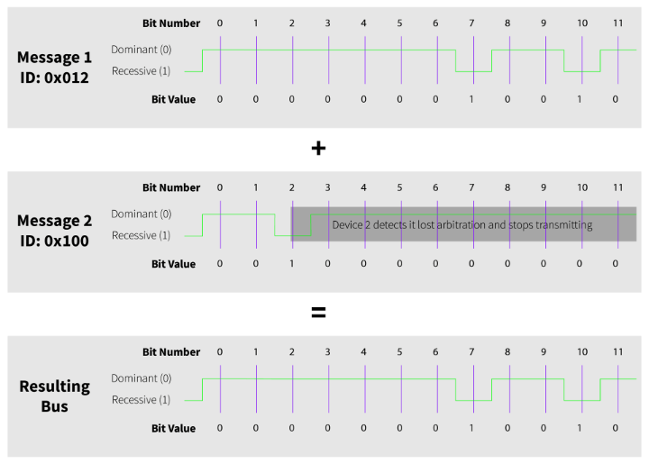
Here’s an example of how arbitration plays out when two devices try to transmit at the same time:
- Device 1 is transmitting message ID 0x012
- Device 2 is transmitting message ID 0x100
Because 0x012 is numerically lower than 0x100, Device 1 has higher priority and will win arbitration.
As both devices begin transmitting their IDs bit by bit, they stay in sync until bit 2, where Device 2 sends a recessive bit (1) while Device 1 sends a dominant bit (0). Device 2 immediately detects that the bus didn’t go into a recessive state as expected—this means another device is asserting dominance.
At that point, Device 2 realizes it has lost arbitration and stops transmitting. The winning message continues unimpeded, and other nodes on the network receive the ID:
- Binary: 0b000000010010
- Hex: 0x012
This is a perfect example of non-destructive arbitration in action—efficient, reliable, and collision-free.
Error Handling
Reliable communication on a CAN network depends on multiple built-in error detection mechanisms:
- Acknowledgment Bits
- Cyclic Redundancy Check (CRC)
- Form and Bit Error Checks
Additionally, CAN nodes constantly synchronize their clocks using transitions from dominant to recessive bits. Precise timing is critical, and each node continuously adjusts its clock to stay in sync with the bus.
Acknowledgment Bits
At the end of every frame, all receiving nodes are expected to transmit a dominant bit to acknowledge successful reception. If the transmitting node doesn’t detect this dominant bit, it assumes the message wasn’t received and may attempt to resend it.
Note: An acknowledgment only confirms that at least one other node saw the message—it doesn’t mean the data was understood or acted upon.
Cyclic Redundancy Check (CRC)
The CRC field in a CAN frame (usually 15 bits) is a checksum calculated from the frame’s contents. The receiver recalculates the CRC and compares it with the received value. If there’s a mismatch, the frame is considered corrupted and is discarded.
Form and Bit Error Checks
While transmitting, each node monitors the bus to ensure the actual signal matches what it expects to see. Some exceptions occur during arbitration, when intentional mismatches are part of the process. But during the data phase, mismatches may indicate that two devices are attempting to transmit different data under the same Message ID—a condition that triggers an error state.
Wrapping Up
Understanding the CAN physical layer is the foundation for building reliable, noise-resistant communication between devices. From bit-level timing and differential signaling to arbitration and error handling, each layer of the protocol is designed for robust and efficient data transfer—even in the harshest environments.
Before wrapping up, here are some basic dos and don’ts to keep your CAN network stable and error-free:
✅ CAN Bus Dos:
- Use twisted pair wiring for CAN_H and CAN_L
- Terminate both ends of the bus with 120-ohm resistors
- Stick to a linear bus layout with short stubs
- Set identical baud rates across all nodes
- Confirm devices support 29-bit IDs if using extended frames
- Design message IDs carefully—lower values have higher priority (most standards like CANopen and J1939 handle this for you)
❌ CAN Bus Don’ts:
- Don’t short CAN_H or CAN_L to ground or VCC
- Don’t short CAN_H and CAN_L to each other
- Don’t let multiple devices send different data using the same message ID
- Don’t mismatch CAN_H and CAN_L wiring on any single node