CAN Isolation – Why It Matters
CAN Bus networks are designed for robust multi-node communication, with built-in reliability and error correction features. However, their open architecture introduces potential risks. In most implementations, all nodes are connected to a shared twisted pair of conductors—CAN High and CAN Low. This design simplifies wiring but also creates a single point of vulnerability: any fault on the bus can affect every connected device.
A voltage spike, persistent dominant state, or misconfigured node can introduce errors that affect the entire network. These risks become more pronounced in electrically noisy environments or systems with long cable runs or distributed power sources. Incorporating isolation into the design of CAN nodes and networks is an effective way to enhance the reliability and fault tolerance of the system.
This post explores common failure modes that stem from the open nature of CAN Bus networks and introduces isolation strategies that reduce risks and improve overall network resilience.
There are two key types of CAN isolation:
- Data Isolation – Protects the network from bit-level issues such as incorrect baud rates, persistent dominant states, invalid data frames, or flooding the bus with invalid data.
- Galvanic Isolation – Prevents damage and communication issues caused by common-mode voltage differences or ground loops, typically by breaking the direct electrical path using optocouplers or digital isolators.
Data Isolation
Because of the open architecture of CAN Bus networks any node can transmit messages at any time. While this is a strength in terms of flexibility, it also introduces potential vulnerabilities. A malfunctioning or malicious node can flood the bus with invalid data, stay in a dominant state, or even spoof legitimate messages—leading to degraded performance or system-wide failures.
To address these risks, gateway devices are commonly used to isolate different CAN segments. In this configuration, the gateway sits between two or more CAN networks and selectively forwards only the necessary messages. This limits the impact of faults on any single segment and allows different parts of the system to operate at varying data rates or follow different communication protocols. It also reduces congestion on individual buses by segmenting traffic intelligently.
A practical example can be found in most modern vehicles: the OBD-II (technicians' diagnostics) port connects to a gateway module, which provides access to diagnostic information without exposing critical internal networks directly to external tools. This setup prevents unauthorized or misbehaving scan tools from interfering with internal vehicle systems.
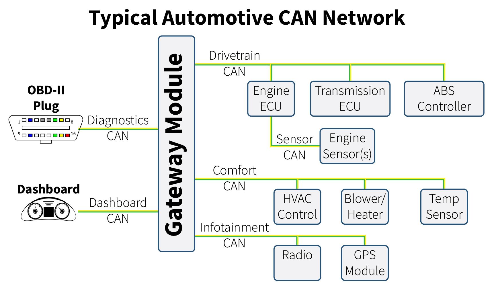
Figure 1: Typical automotive CAN network topology.
Another application of data isolation is during reverse engineering. For instance, a CAN datalogger or repeater can isolate a specific node and replicate its traffic across two separate CAN buses. This allows engineers to analyze message behavior in a controlled environment.
Figure 2 illustrates how our BusEye CL2 can facilitate this setup—bridging two buses, forwarding messages, and logging data to an SD card or USB for analysis.
In a future post, we’ll explore how to use the CL2 for data isolation between CAN segments, with live message forwarding and onboard logging to support diagnostics, testing, or reverse engineering tasks.
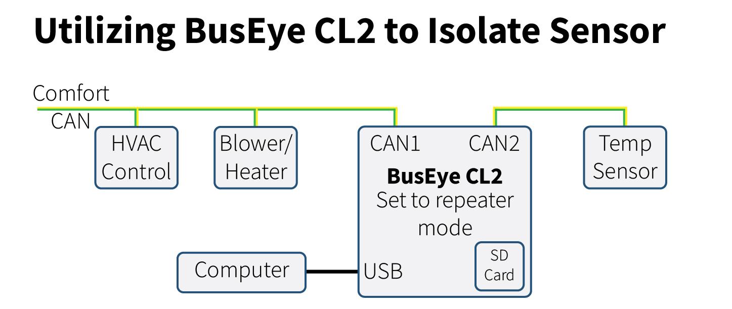
Figure 2: How to isolate a sensor using a BusEye CL2
Galvanic Isolation
Galvanic isolation, also known as electrical isolation, prevents voltage spikes and ground potential differences from propagating through a CAN Bus network. This is particularly important in two scenarios: (1) systems with sensitive measurement equipment, where noise immunity is critical, and (2) systems with multiple power domains or distributed power supplies, where differing ground references can lead to communication failures or even hardware damage.
By isolating a CAN network into separate segments, unwanted transients and common-mode voltages can be contained—protecting nodes and preserving reliable communication.
There are two common types of galvanic isolation technologies used in CAN systems: (Note both of the examples below are direct signal isolators without microcontrollers.)
- Optical Isolation: These isolators use light to transmit signals between the transmitting and receiving sides. For example, devices like the PCAN-Optoadapter offer several hundred volts of isolation, suitable for moderate industrial applications.
- Inductive Isolation: These use magnetic coupling (transformers or coil-based structures) to achieve higher isolation levels, often up to 5000 volts. An example is the CAN-ISO-2500, which provides robust isolation for demanding environments.
Beyond the isolation technology, CAN isolators can be implemented in two main ways:
- Microcontroller-Based Repeaters – These devices read messages on one side, buffer them, and retransmit them on the other side. Because the two sides of the network are decoupled, this approach introduces latency, but offers flexibility in filtering, rate conversion, and datalogging. Note: a repeater device must also be rated for electrical isolation to be used in this way.
- Direct Signal Isolation – These devices pass the dominant and recessive levels of the CAN signal through isolation components (e.g., optocouplers or digital isolators). While this method allows real-time communication and supports arbitration, it requires careful circuit design to maintain correct CAN signal behavior, especially for the arbitration phase of the CAN messge. One of the key advantages of direct signal isolation is that it typically does not require any baud rate configuration. These isolators can operate across a wide range of data rates, making them highly flexible and compatible with various systems without needing baud rate-specific hardware.
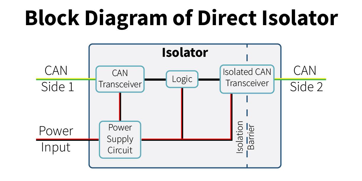
Figure 3: Simplified diagram for a direct galvanic Isolator.
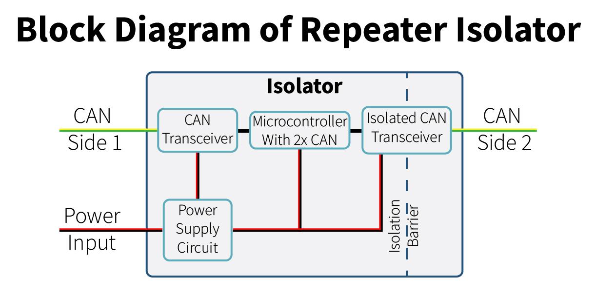
Figure 4: Simplified diagram of a microcontroller-based isolator
Both approaches have their advantages depending on the system requirements, and careful consideration should be given to latency tolerance, voltage isolation ratings, and desired diagnostic capabilities.
System Example: Sensitive Measurement Equipment
In this example, a precision measurement device is used to transmit data over a shared CAN Bus. These types of devices—such as strain gauges, temperature sensors, or analog-to-digital converters—can be highly sensitive to electrical noise. If other nodes on the network generate transients or noise due to switching components, long cable runs, or electromagnetic interference, the accuracy of the measurements can be compromised.
By adding a CAN Bus isolator between the measurement device and the rest of the network, electrical noise from other nodes is effectively blocked. The isolator maintains data communication while breaking the direct electrical connection, protecting the integrity of the measurement signals and helping to ensure consistent, high-quality data capture.
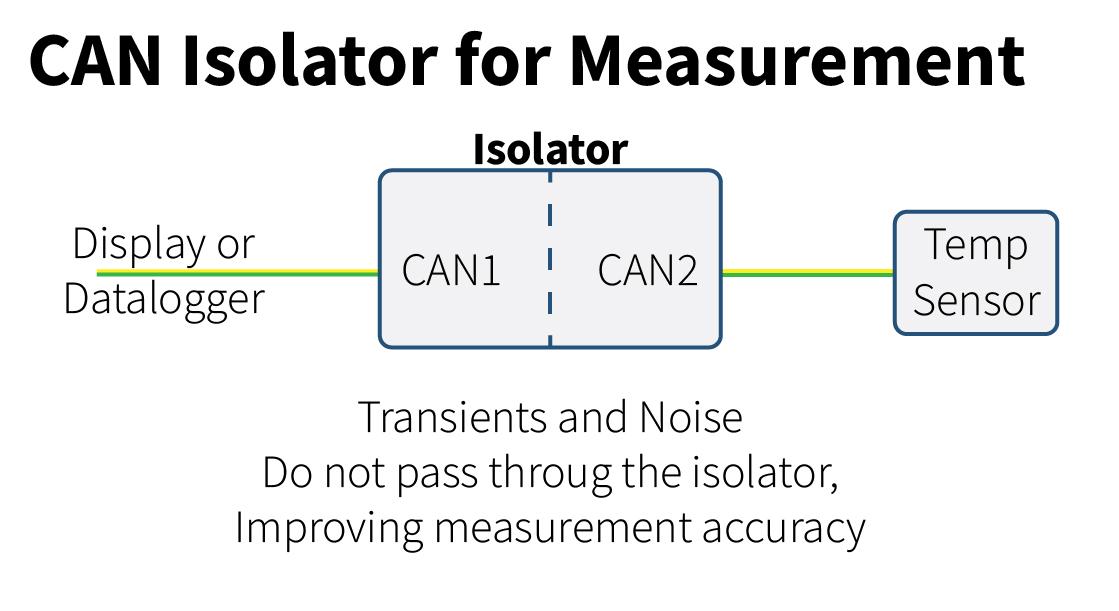
Figure 5: Sensitive measurement using galvanic CAN isolator
System Example: Multiple Power Supplies
In this scenario, consider an electric vehicle (EV) that has two distinct power domains: a high-voltage system for driving the traction motors, and a low-voltage system for powering control units, dashboard electronics, and the Human Machine Interface (HMI). Each domain has its own ground reference, and connecting them directly via a non-isolated CAN Bus would allow ground loops or high-voltage transients to propagate through the communication lines.
A CAN Isolator placed between the high-voltage motor controller and the low-voltage control system allows safe data exchange while preventing harmful electrical disturbances from crossing between power domains. This ensures that noise or voltage spikes originating on the motor side cannot reach and damage sensitive components on the control side.
Without a CAN Isolator in place, the CAN transceiver chips in either the high-voltage (HV) or low-voltage (LV) devices could be exposed to dangerous voltage levels, leading to hardware failure and communication breakdowns.
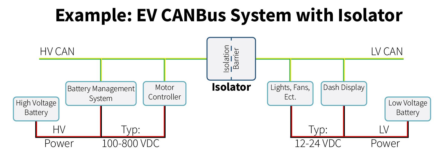
Figure 6: Example electric vehicle system diagram with isolator
Conclusion
Isolating segments of a CAN Bus network is essential for maintaining consistent, reliable communication—especially in systems exposed to electrical noise, varying ground potentials, or high-power components. Whether the goal is to protect sensitive measurement devices, segment high-voltage and low-voltage systems, or simply improve fault tolerance, proper isolation can significantly reduce risk and simplify debugging.
During the early stages of system design, always evaluate whether data isolation, galvanic isolation, or both are required. Incorporating isolation upfront can prevent costly failures, improve system safety, and increase long-term maintainability.
As systems become more complex, thoughtful isolation strategies are not just a best practice—they're a key part of robust CAN Bus architecture.