Introduction
Welcome back to the CAN Bus for Engineers series!
In this post, we’re going to dive into what makes a device able to communicate on the CAN network. Specifically, we’ll explore the core hardware and software components of a CAN node, and the interactions between them that allow successful communication. Whether you're integrating off-the-shelf ECUs into a network or building your first CAN-enabled sensor, understanding node architecture is key.
🧩 What Is a CAN Node?
A CAN node is any device that connects to the bus and can send and/or receive CAN frames. This could be something as simple as a temperature sensor or as complex as an engine control unit (ECU). As long as it can transmit and receive CAN messages, it qualifies as a node.
Some devices may connect to multiple CAN networks simultaneously—each of those connections is considered a separate node, even if they originate from the same physical hardware.
Real-world analogy: Think of each node as a participant in a group chat. Each one has a voice to transmit and ears to receive. On a CAN bus, they “shout” information to each other using CAN frames, as discussed in our previous post on the physical layer.
Core Components of a CAN Node
A CAN node is composed of both hardware and software components. The modularity and reusability of these components make it easy to scale and replicate CAN-enabled devices across multiple product lines or applications.
🔧 Hardware Components
The hardware components of a CAN node work together in a tightly coordinated sequence to enable communication on the bus. The microcontroller, (MCU), which may have an integrated CAN controller, orchestrates message creation, transmission, and reception. If a standalone CAN controller is used, it communicates with the MCU over a serial interface such as SPI and handles tasks like message filtering, CRC checks, and error detection. The CAN controller passes transmit and receive signals to the CAN transceiver, which converts digital logic levels to the differential voltages required on the physical CAN bus lines (CAN_H and CAN_L). These lines connect to other nodes via wires and connectors, often through shielded or twisted-pair wiring. Supporting all of these components is the power and protection circuitry, which ensures that the node operates within a stable electrical environment, guards against voltage spikes and electromagnetic interference, and provides necessary filtering and conditioning to keep data transmission reliable.
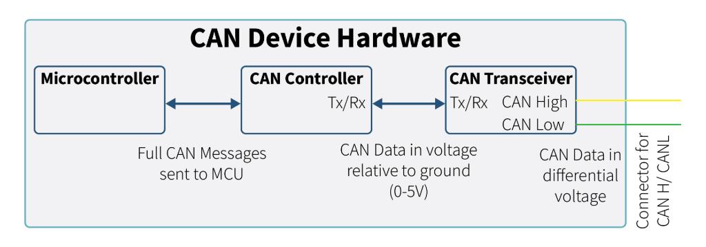
Figure 1: Physical components of a CAN Node
- Microcontroller (MCU) or Embedded Computer
- Prepares messages and handles received data.
- May include a built-in CAN controller.
- Example: PIC18F258 includes a CAN 2.0B Compatible controller.
- CAN Controller (if not integrated)
- Manages frame formatting, message filtering, error checking.
- Requires a stable clock source for synchronization.
- Example: MCP2515 Standalone CAN Controller with SPI interface for communicating with MCU.
- CAN Transceiver
- Physical Connections
- Includes CAN_H and CAN_L wires, termination resistors, and physical connectors.
- Power Supply and Protection
- Voltage regulators, ESD protection diodes, filtering capacitors.
- Ensures stable operation and robustness against electrical noise or transients.
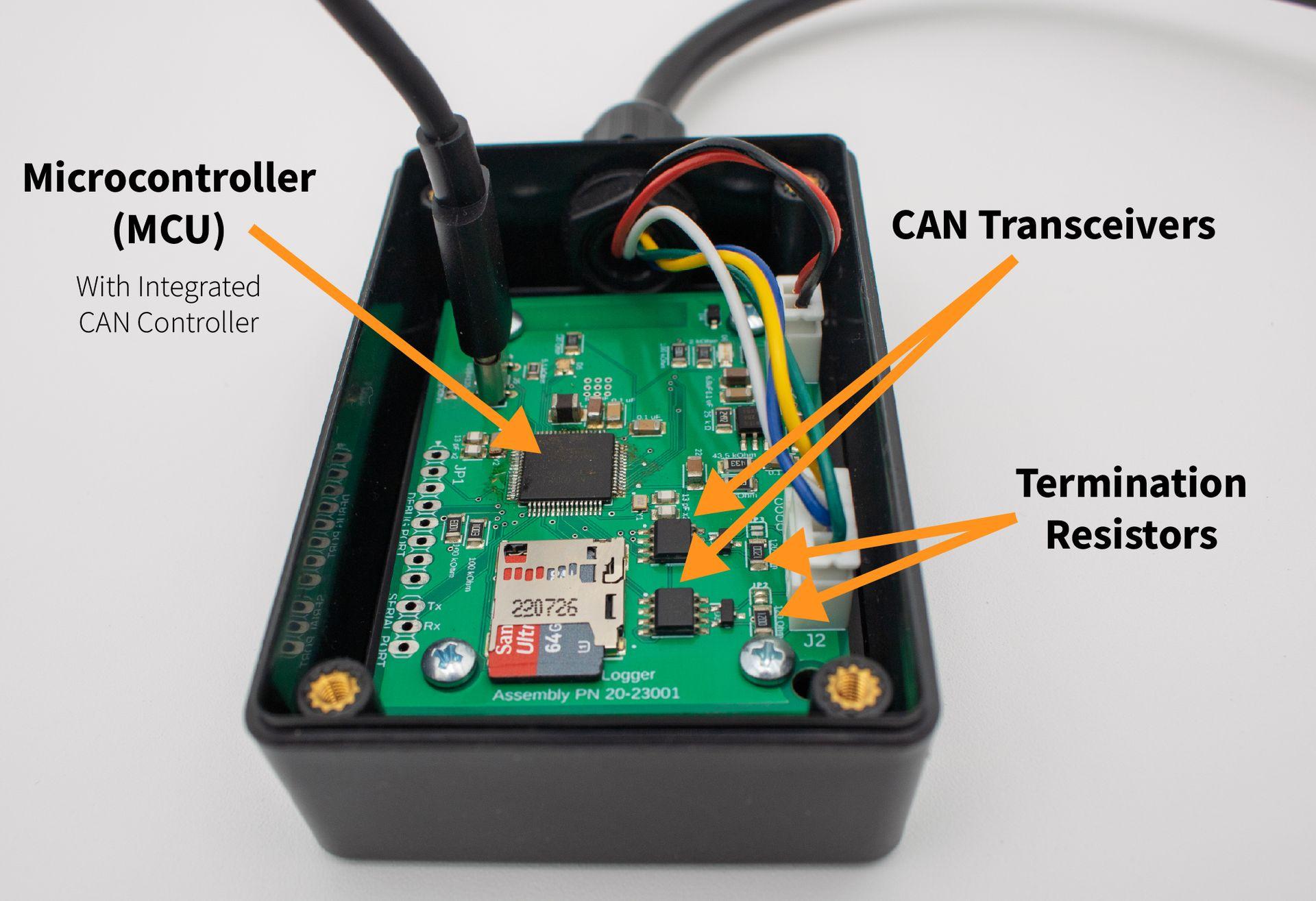
Figure 2: Components on a CAN Device
🧠 Software Components
The software components of a CAN node function as the intelligence behind the hardware, coordinating how data is generated, processed, and exchanged over the CAN network. The CAN driver or stack initializes the hardware peripheral, configures the bit timing, and manages interrupts related to message events. It serves as the foundation upon which the rest of the software operates. Sitting on top of the driver is the message handling logic, which applies filters, manages buffer queues, and ensures that only relevant messages are passed along to or from the application. This layer abstracts away the low-level complexity of the CAN protocol and provides a structured interface for the application to work with. The application layer contains the user-defined behavior that gives purpose to the node—whether that's sending sensor data, issuing control commands, or reacting to incoming messages. Together, these software layers work in tandem to support efficient and reliable communication within the constraints of the CAN protocol.
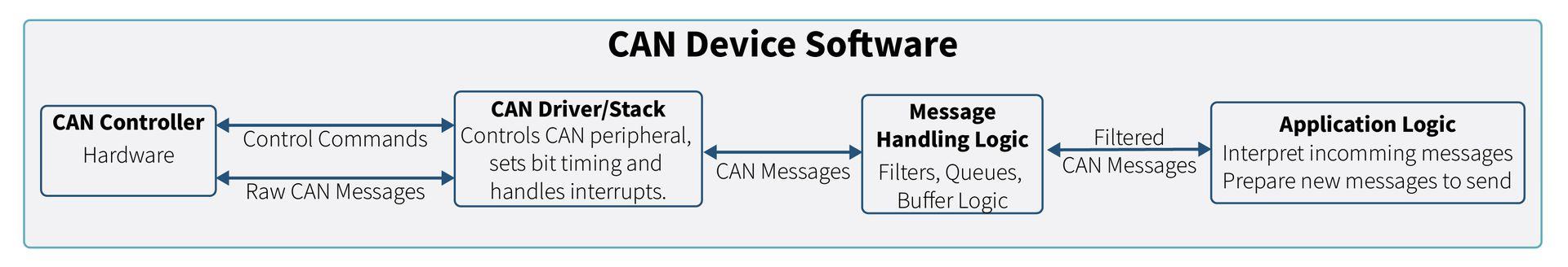
Figure 3: Softare Diagram of CAN Node
- CAN Driver/Stack
- Initializes CAN peripheral, sets bit timing, and handles interrupts.
- Often provided by MCU manufacturers but can be customized.
- Message Handling Logic
- Manages filters, queues, and buffer logic.
- Interfaces between the CAN driver and the application.
- Application Layer
- Contains user-defined logic to interpret incoming messages or prepare outgoing ones.
- Examples: sensor measurements, actuator commands, status reporting.
⚙️ Basic Node Behaviors
📤 Transmit
When a node needs to send data, it loads a CAN frame into the transmit buffer, where it waits for its turn to access the bus. Arbitration then takes place to determine which node has priority and gets to transmit first. Once the frame wins arbitration, it is sent onto the bus, and acknowledgment and the error-checking mechanisms help ensure it was successfully delivered.
The typical flow for transmission follows this path: Application → Tx Buffer → CAN Controller → CAN Transceiver → CAN Wires.
📥 Receive
When a CAN frame arrives on the bus, it is first acknowledged and checked for integrity using the CRC. The CAN controller then applies hardware-level filtering to determine whether the frame should be processed or discarded. If it passes the filter, the message is handed off to the microcontroller, where the application layer can interpret and act on it. This process allows nodes to efficiently handle only the data relevant to their function.
Typical flow for reception follows this path: CAN Wires → CAN Transceiver → CAN Controller → Rx Buffer → Application.
⚠️ Error Handling
CAN controllers are designed with robust error detection and correction mechanisms. If a transmission error is detected, the frame is automatically queued for retransmission. Each node maintains internal error counters that track transmit and receive errors. If error thresholds are exceeded, the node may enter a "bus-off" state to prevent further disruption on the network.
Well-designed systems expose these statuses to developers or users, allowing for diagnostics or fallback strategies in case of persistent communication faults.
🤖 Application Logic
At the core of a CAN node’s usefulness is its application logic—the part that gives meaning to the messages it sends and receives. This logic is highly customizable and specific to the device’s purpose. For example, a pressure sensor node may periodically transmit current pressure data, while an ECU could aggregate multiple sensor readings and transmit them as a single status frame. By interpreting incoming data and triggering appropriate actions, the application logic enables intelligent, responsive network behavior.
Node Selection Considerations
If you're assembling a CAN network, consider the following:
Baud rate compatibility: Some devices only support fixed baud rates.
Termination resistors: Know which nodes require internal termination and whether they are configurable.
Isolation requirements: For example, electric vehicles may require isolated CAN segments to prevent high-voltage transients.
CAN ID uniqueness: Ensure each transmitting node uses a unique CAN ID to avoid bus conflicts.
Protocols: Standards like CANopen and J1939 help manage node behavior and message IDs.
Node Design Considerations
If you’re building your own node consider:
Physical design: Ensure connectors and housing are robust and compatible with the existing system.
Termination options: Consider jumpers or switches to enable/disable termination resistors.
Transceiver robustness: Select components that tolerate electrical faults appropriate to the system voltage.
Bit timing accuracy: Verify that your clock sources and software bit timing match the network.
Low power features: Decide how the node wakes up—via CAN traffic or external triggers (e.g., vehicle run or ignition switch).
📌 Key Takeaways
A CAN node combines both hardware—including an MCU, CAN controller, and transceiver—and software, such as drivers, message handling logic, and application code, to enable communication over a CAN network. Reliability in CAN systems depends on the correct setup of both the physical circuitry and the firmware configuration. By mastering node fundamentals, developers can design and troubleshoot robust and responsive systems that perform well in real-world environments. Making informed design decisions early—like choosing the right transceivers, ensuring correct bit timing, and planning for termination and isolation—can significantly reduce issues encountered during testing and implementation of CAN bus networks.
Stay tuned for our next post, where we’ll explore how isolating CAN Busses can improve reliability in designing systems.